Note
Go to the end to download the full example code.
45-kW IM, V/Hz control, mechanical impedance#
This example measures the mechanical impedance of a 45-kW induction machine (IM) drive under open-loop V/Hz control and under observer-based V/Hz (O-V/Hz) control. The machine parameters correspond to [1].
from math import inf

import matplotlib.pyplot as plt
import motulator.drive.control.im as control
import numpy as np
from motulator.drive import model, utils

from motulator_impedance import drive
Compute base values based on the nominal values.
nom = utils.NominalValues(U=400, I=81, f=50, P=45e3, tau=291)
base = utils.BaseValues.from_nominal(nom, n_p=2)
Configure the measurement.
meas_cfg = drive.MeasurementCfg(
    abs_w_e=0.002 * base.w_M, freqs=np.geomspace(1, 500, 50)
)
Configure the system model. The rotor speed is imposed, i.e., no mechanical system is used. The operating-point speed is 0.25 p.u.
w_M0 = 0.25 * base.w_M
par = model.InductionMachineInvGammaPars(
    n_p=2, R_s=60e-3, R_R=30e-3, L_sgm=2.2e-3, L_M=24.5e-3
)
mechanics = model.ExternalRotorSpeed()
mechanics.set_external_rotor_speed(w_M0)
converter = model.VoltageSourceConverter(u_dc=540)
mdl = model.Drive(model.InductionMachine(par), mechanics, converter)
Configure open-loop V/Hz control without stator resistance compensation and slip compensation.
est_par = control.InductionMachineInvGammaPars(n_p=2, R_s=0, R_R=0, L_sgm=0, L_M=inf)
cfg = control.ObserverBasedVHzControllerCfg(
    psi_s_nom=base.psi, i_s_max=inf, alpha_f=0, alpha_tau=0, alpha_psi=0
)
open_loop_ctrl = control.VHzControlSystem(
    control.ObserverBasedVHzController(est_par, cfg)
)
Configure O-V/Hz control.
cfg = control.ObserverBasedVHzControllerCfg(psi_s_nom=base.psi, i_s_max=1.5 * base.i)
ovhz_ctrl = control.VHzControlSystem(control.ObserverBasedVHzController(par, cfg))
ctrls = {"Open-loop V/Hz": open_loop_ctrl, "O-V/Hz": ovhz_ctrl}
Measure the mechanical impedance at no load, i.e., the speed reference equals the rotor speed, and plot the results.
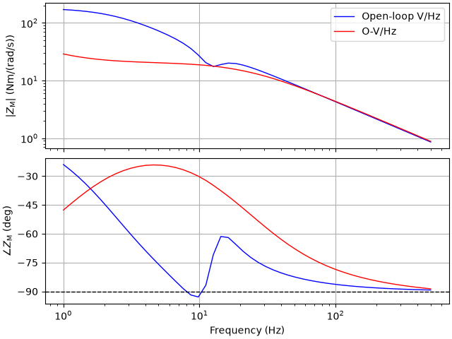
The phase of the mechanical impedance under open-loop V/Hz control is below -90° around 10 Hz, i.e., the impedance is non-passive. Instead of damping torsional vibrations, the drive may amplify them. Under O-V/Hz control, the impedance is passive in the measured frequency range.
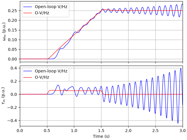
Simulate the acceleration to the operating point with rigid mechanics. Under open-loop V/Hz control, the drive becomes unstable, while it is stable under O-V/Hz control.
if __name__ == "__main__":
    times = np.array([0, 0.5, 1.5, 3])
    values = np.array([0, 0, 1, 1]) * w_M0
    _, (ax1, ax2) = plt.subplots(2, 1, sharex=True)
    for label, ctrl in ctrls.items():
        mdl = model.Drive(
            model.InductionMachine(par),
            model.MechanicalSystem(J=0.49),
            model.VoltageSourceConverter(u_dc=540),
        )
        ctrl.set_speed_ref(utils.SequenceGenerator(times, values))
        res = model.Simulation(mdl, ctrl).simulate(t_stop=3)
        ax1.plot(res.mdl.t, res.mdl.mechanics.w_M / base.w_M, label=label)
        ax2.plot(res.mdl.t, res.mdl.machine.tau_M / base.tau, label=label)
    ax1.set_ylabel(r"$\omega_\mathrm{m}$ (p.u.)")
    ax2.set_ylabel(r"$\tau_\mathrm{m}$ (p.u.)")
    ax2.set_xlabel("Time (s)")
    ax2.set_xlim(0, 3)
    ax1.legend(loc="upper left")
    ax2.legend(loc="upper left")
    plt.show()
References
Total running time of the script: (2 minutes 28.009 seconds)