Flux-Vector Control#
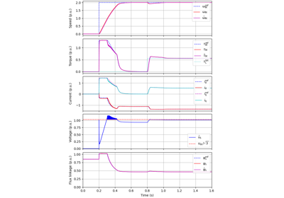
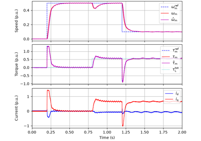
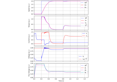
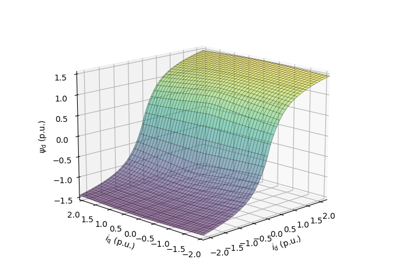
These examples demonstrate flux-vector control (FVC) of electric machine drives [1]. In the implemented control system, decoupling between the stator flux and torque channels are used according to [2]. Furthermore, the stator flux magnitude and the electromagnetic torque are selected as controllable variables. The implementations correspond to [3] for synchronous machines and [4] for induction machines. The magnetic saturation is modeled and taken into account in control. The examples with GradNet magnetic models [5], based on gradient networks [6], which model the current or flux linkage map as the gradient of the magnetic energy or co-energy, use models trained from measured and FEM data with the related package motulator-gradnet.
References