Note
Go to the end to download the full example code.
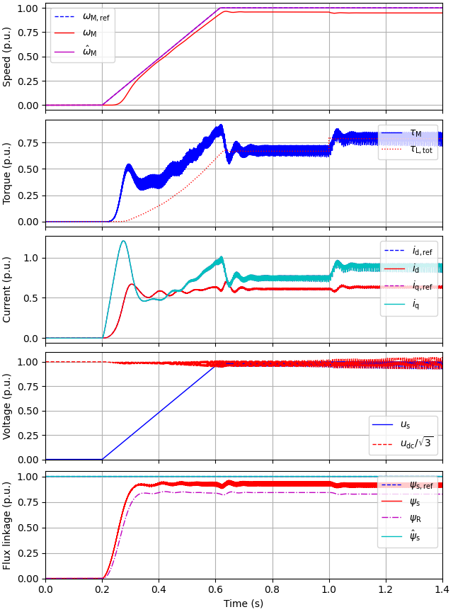
2.2-kW induction motor, diode bridge#
A diode bridge, stiff three-phase grid, and a DC link is modeled. The control system is configured as pure open-loop V/Hz control.
Compute base values based on the nominal values.
nom = utils.NominalValues(U=400, I=5, f=50, P=2.2e3, tau=14.6)
base = utils.BaseValues.from_nominal(nom, n_p=2)
Configure the system model.
par = model.InductionMachineInvGammaPars(
    n_p=2, R_s=3.7, R_R=2.1, L_sgm=0.021, L_M=0.224
)
machine = model.InductionMachine(par)
k = 1.1 * nom.tau / base.w_M**2  # Quadratic load torque profile
mechanics = model.MechanicalSystem(J=0.015, B_L=lambda w_M: k * abs(w_M))
converter = model.FrequencyConverter(C_dc=235e-6, L_dc=2e-3, U_g=nom.U, f_g=nom.f)
mdl = model.Drive(machine, mechanics, converter, pwm=True)
Configure the control system as open-loop V/Hz control.
est_par = control.InductionMachineInvGammaPars(n_p=2, R_s=0, R_R=0, L_sgm=0, L_M=inf)
cfg = control.ObserverBasedVHzControllerCfg(
    psi_s_nom=base.psi, i_s_max=inf, alpha_f=0, alpha_tau=0, alpha_psi=0
)
vhz_ctrl = control.ObserverBasedVHzController(est_par, cfg)
ctrl = control.VHzControlSystem(vhz_ctrl, slew_rate=2 * pi * 60)
Set the speed reference and the external load torque.
Create the simulation object, simulate, and plot the results in per-unit values.
sim = model.Simulation(mdl, ctrl)
res = sim.simulate(t_stop=1.4)
# sphinx_gallery_thumbnail_number = 2
utils.plot(res, base)
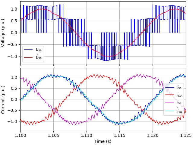
utils.plot_stator_waveforms(res, base, t_lims=(1.1, 1.125))
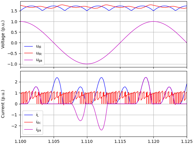
utils.plot_dc_bus_waveforms(res, base, t_lims=(1.1, 1.125))
Note
The DC link of this particular example is actually unstable at 1-p.u. speed at the rated load torque, since the inverter looks like a negative resistance to the DC link. You can notice this instability if simulating a longer period (e.g. set t_stop=2). For analysis, see e.g., [1].
References
Total running time of the script: (0 minutes 13.651 seconds)