Drives#
A collection of example scripts for machine drives.
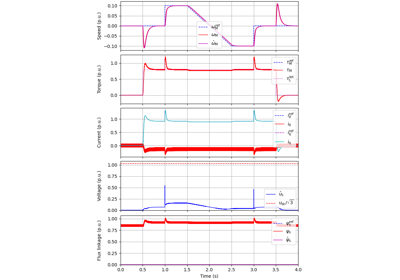
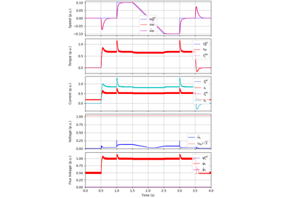
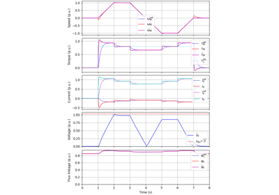
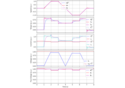
Flux-Vector Control#
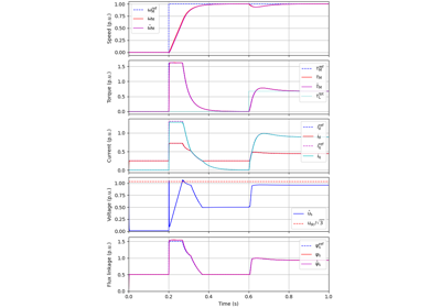
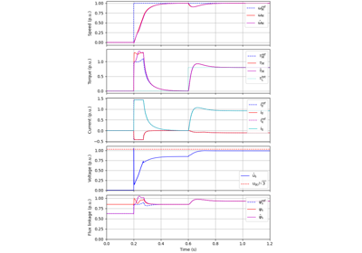
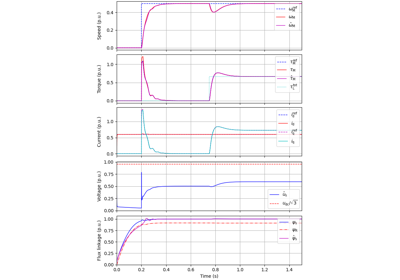
These examples demonstrate flux-vector control (FVC) of electric machine drives [1]. In the implemented control system, decoupling between the stator flux and torque channels are used according to [2]. Furthermore, the stator flux magnitude and the electromagnetic torque are selected as controllable variables. The implementations correspond to [3] for synchronous machines and [4] for induction machines. The magnetic saturation is modeled and taken into account in control.
References
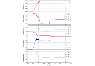
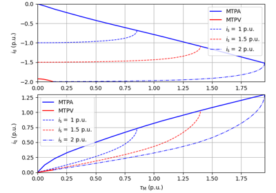
Current-Vector Control#
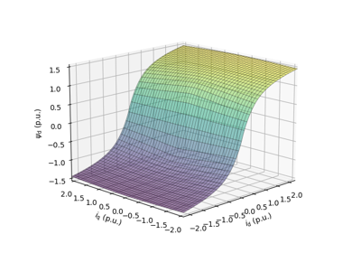
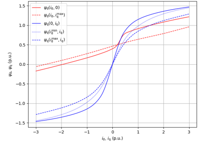
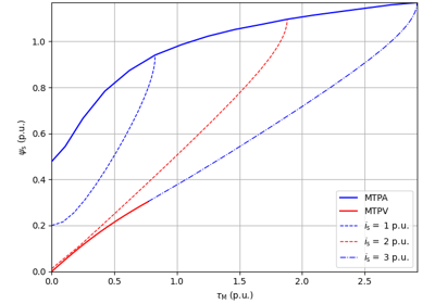
These examples are for current-vector control (CVC) of induction and synchronous machines. The magnetic saturation model of an induction machine is also demonstrated (2.2-kW saturated IM, CVC) as well as computation of control lookup tables for synchronous machines (5.1-kW saturated PM-SyRM, CVC).
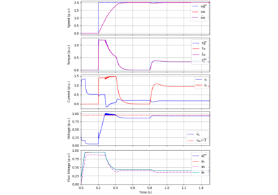
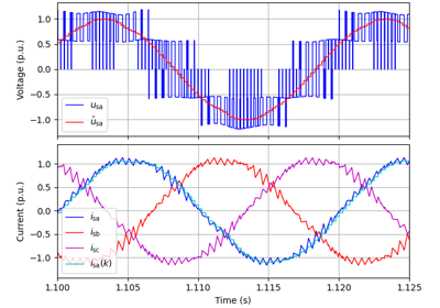
V/Hz Control#
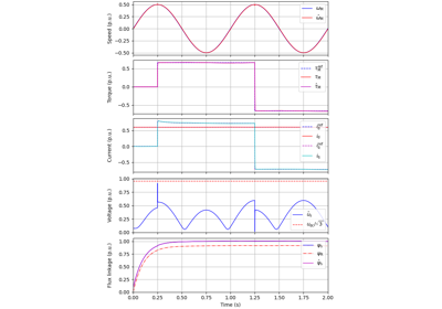
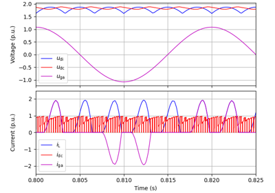
These examples demonstrate observer-based V/Hz (O-V/Hz) control for synchronous machines [5] and induction machines [6]. The example 2.2-kW IPMSM, 2-mass mechanics, O-V/Hz control demonstrates the use of a two-mass mechanics model. Furthermore, the examples 2.2-kW IM, diode bridge, V/Hz control and 2.2-kW IM, LC filter, V/Hz control show operation of an induction machine under pure open-loop V/Hz control with a diode front-end rectifier and with an LC filter, respectively.
References
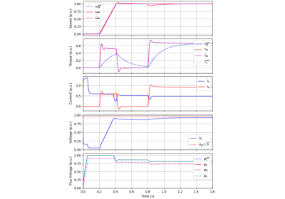
Signal Injection#
These examples demonstrate a square-wave signal injection for low-speed operation based on [7]. Cross-saturation errors are compensated for using flux maps [8]. A phase-locked loop is used to track the rotor position. For a wider speed range, signal injection could be combined to a model-based observer.
References