Note
Go to the end to download the full example code.
10-kVA converter#
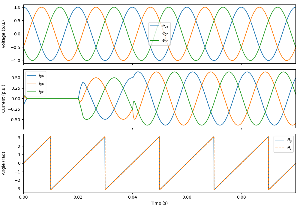
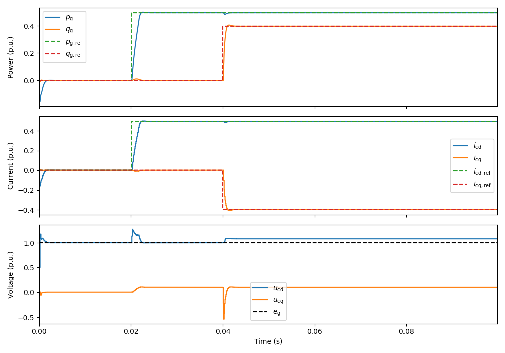
This example simulates a grid-following-controlled converter connected to an L filter and a strong grid. The control system includes a phase-locked loop (PLL) to synchronize with the grid, a current reference generator, and a PI-based current controller.
from motulator.grid import control, model, utils
Compute base values based on the nominal values.
nom = utils.NominalValues(U=400, I=14.5, f=50, P=10e3)
base = utils.BaseValues.from_nominal(nom)
Configure the system model.
# Filter and grid
ac_filter = model.LFilter(L_f=0.2 * base.L)
ac_source = model.ThreePhaseSource(w_g=base.w, e_g=base.u)
converter = model.VoltageSourceConverter(u_dc=650)
mdl = model.GridConverterSystem(converter, ac_filter, ac_source)
Configure the control system.
inner_ctrl = control.CurrentVectorController(i_max=1.5 * base.i, L=0.2 * base.L)
ctrl = control.GridConverterControlSystem(inner_ctrl)
Set the time-dependent reference and disturbance signals.
# Set the active and reactive power references
ctrl.set_power_ref(lambda t: (t > 0.02) * 5e3)
ctrl.set_reactive_power_ref(lambda t: (t > 0.04) * 4e3)

# Uncomment lines below to simulate an unbalanced fault (add negative sequence)
# from math import pi
# mdl.ac_source.e_g = 0.75 * base.u
# mdl.ac_source.e_g_neg = 0.25 * base.u
# mdl.ac_source.phi_neg = -pi / 3
Create the simulation object, simulate, and plot the results in per-unit values.
sim = model.Simulation(mdl, ctrl)
res = sim.simulate(t_stop=0.08)
utils.plot_control_signals(res, base)
utils.plot_grid_waveforms(res, base, plot_pcc_voltage=False)


# Uncomment line below to plot locus of the grid voltage space vector
# utils.plot_voltage_vector(res, base)
Total running time of the script: (0 minutes 0.961 seconds)