V/Hz Control#
In V/Hz control, the machine is driven at the frequency given by the speed reference, without a speed controller. Two methods are available: open-loop V/Hz control for induction machines and observer-based V/Hz control for synchronous machines [Tiitinen et al., 2025] and induction machines [Tiitinen et al., 2025]. Both are used with the VHzControlSystem class, which limits the rate of change of the speed reference.
Open-Loop V/Hz Control#
In open-loop V/Hz control, the stator voltage reference is given by a V/Hz curve as a function of the stator angular frequency \(\omegas = \np\omegaMref\), where \(\omegaMref\) is the rate-limited speed reference. The reference is given in coordinates rotating at \(\omegas\). The linear V/Hz curve is
where \(\psi_\mathrm{s}^\mathrm{nom}\) is the nominal stator flux linkage. In the steady state, the stator voltage equation in (1) is \(\us = \Rs\is + \jj\omegas\psis\) in these coordinates. Hence, the curve (1) gives the nominal stator flux linkage, if the resistive voltage drop is negligible. At low frequencies, the resistive voltage drop reduces the flux linkage. At no load, the stator current is \(\is = \psis/\Ls\), where \(\Ls\) is the stator inductance, and the curve
gives the nominal stator flux linkage at all frequencies. The slip is not compensated for, i.e., the rotor speed deviates from its reference depending on the load.
The motulator.drive.control.im.OpenLoopVHzController class takes the V/Hz curve as a function. See the examples 2.2-kW IM, LC filter, V/Hz control and 2.2-kW IM, diode bridge, V/Hz control.
Observer-Based V/Hz Control#
Figure 1 shows the structure of observer-based V/Hz control, which is available in the motulator.drive.control.sm.ObserverBasedVHzController class for synchronous machines and in the motulator.drive.control.im.ObserverBasedVHzController class for induction machines. The structure is that of flux-vector control, see Flux-Vector Control, with the following differences:
The observer does not estimate the speed. The rate-limited speed reference is used in its place, \(\hatomegam = \omegamref\), see Observers.
The torque reference is not given by a speed controller, but it is the low-pass-filtered torque estimate
(3)#\[ \tauMref = \frac{\alpha_\mathrm{f}}{s + \alpha_\mathrm{f}}\hattauM\]where \(\alpha_\mathrm{f}\) is the bandwidth of the filter. The reference generation limits this reference, see Reference Generation.
The torque reference thus equals the torque estimate in the steady state, and the torque control error is the high-pass-filtered torque estimate with the opposite sign, \(\tauMref - \hattauM = -[s/(s + \alpha_\mathrm{f})]\hattauM\). The stator flux magnitude is controlled as in flux-vector control.
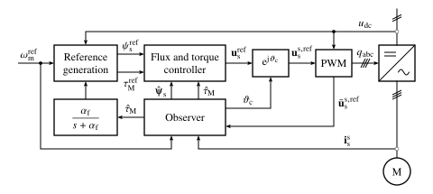
Figure 1: Observer-based V/Hz control. For induction machines, the reference generation uses the estimates \(\hatomegas\) and \(\hatabspsiR\) from the observer instead of \(\omegamref\). The flux and torque controller uses the stator flux linkage and torque estimates shown in the figure as well as other estimates from the observer, such as the stator current and the angular speed of the coordinate system. The observer uses the realized voltage \(\usreflim\) (in stationary coordinates) obtained from the PWM, taking into account the voltage limitation and the computational delay.#
Figure 1: Observer-based V/Hz control. For induction machines, the reference generation uses the estimates \(\hatomegas\) and \(\hatabspsiR\) from the observer instead of \(\omegamref\). The flux and torque controller uses the stator flux linkage and torque estimates shown in the figure as well as other estimates from the observer, such as the stator current and the angular speed of the coordinate system. The observer uses the realized voltage \(\usreflim\) (in stationary coordinates) obtained from the PWM, taking into account the voltage limitation and the computational delay.#
See the examples in V/Hz Control.